English
 中文简体
中文简体 русский
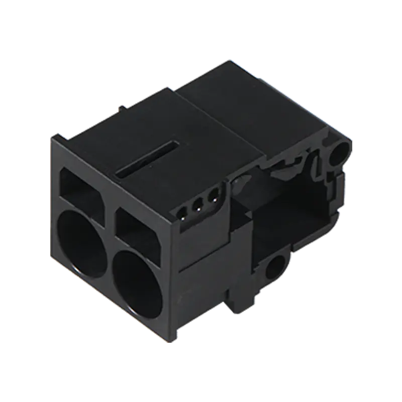

Design engineers reviewing a new stacked-board layout keep running into the same design bottleneck: pitch tolerance, stacking height, and current rating on board to board PCB connectors rarely all line up on a single off-the-shelf part. Sourcing teams supplying this category now field detailed engineering questions before a quote goes out, since a connector that fits one board spacing often fails an unrelated requirement like mating cycle life or contact resistance under vibration.
Pitch Tolerance and Stacking Height
Pitch spacing shapes a board layout more heavily than several other dimensions on a connector datasheet. A 0.5mm pitch part packs far more contacts into a given footprint than a 1.0mm or 2.0mm option, but tighter pitch also raises the risk of solder bridging during reflow, which pushes design teams toward larger pitch options whenever board space allows it. Buyers sourcing board to board PCB connectors for dense consumer electronics typically accept the reflow risk in exchange for the contact density, while industrial customers building ruggedized equipment often favor a wider pitch that tolerates less precise assembly lines.
Stacking height, the gap a connector sets between two parallel boards, follows a similar trade-off. Shorter stack heights save vertical space inside a housing but leave less room for components mounted underneath the top board, so mechanical engineers and PCB layout teams frequently negotiate this dimension back and forth before locking a design. Connector manufacturers serving this space now offer stacking heights in fine increments rather than a handful of fixed options, since a millimeter of clearance can decide whether a heat sink or shielding can fit beside the connector.
|
Connector Attribute |
Design Trade-off |
Common Range |
|
Pitch spacing |
Contact density vs. reflow risk |
0.4mm to 2.0mm |
|
Stacking height |
Vertical clearance vs. board space |
3mm to 15mm |
|
Contact plating |
Cost vs. corrosion resistance |
Gold, tin, or selective plating |
|
Mating cycles |
Durability vs. contact force |
10 to 100+ insertions |
Signal Integrity at Higher Data Rates
As data rates climb, a connector stops being a passive mechanical link and starts behaving like an active part of the signal path. Impedance mismatch at the contact interface introduces reflections that degrade signal quality long before the rest of a circuit shows an obvious fault, so high-speed board to board PCB connectors now carry impedance-controlled contact geometry specifically tuned for differential pairs. Ground contact placement matters just as much here, since insufficient grounding around signal pins lets crosstalk creep into adjacent channels on a densely packed connector.
Shielding options add another layer to this conversation. Metal shrouds or grounded shield fingers around a connector body reduce electromagnetic interference for boards carrying sensitive RF or high-speed digital signals, and buyers increasingly request insertion loss curves alongside a standard datasheet before committing to a design that depends on clean signal transmission across the connector interface.
Mounting Methods and Assembly Line Fit
SMT and through-hole mounting styles pull a design in different directions depending on the assembly line a customer runs. Surface-mount board to board PCB connectors suit high-volume reflow lines and lower profile designs, while through-hole variants hold up better under mechanical stress and repeated mating in equipment serviced in the field. Some manufacturers now offer hybrid mounting with through-hole solder tails for strength paired with surface-mount pads for coplanarity, giving assembly lines flexibility without a full tooling change for these SMT connectors.
Coplanarity tolerance during reflow deserves attention here too, since a connector that sits even slightly uneven across its footprint can produce open solder joints invisible to a routine visual inspection. Buyers sourcing connectors for automated lines increasingly request coplanarity test data rather than relying on a general mounting-type description.
Where Application Demands Shape Connector Choice
Automotive and industrial buyers push different requirements onto the same connector family. Automotive-grade PCB interconnect solutions need to survive vibration profiles, temperature cycling from engine-bay conditions, and contact plating resistant to fretting corrosion over years of service, while consumer electronics prioritize thinner profiles and lower unit cost over that same durability margin. Telecom equipment sits somewhere between the two, favoring high-speed board-to-board connectors with strong shielding but without the wide temperature range automotive parts require.
HTN Relay, supplying components in this category, structures its board to board PCB connectors around documented pitch tolerance, stacking height options, and mating-cycle data rather than a single generic spec sheet, giving design engineers a clearer reference point when matching a connector to a specific board layout rather than adjusting the layout around a connector's limitations.