English
 中文简体
中文简体 русский

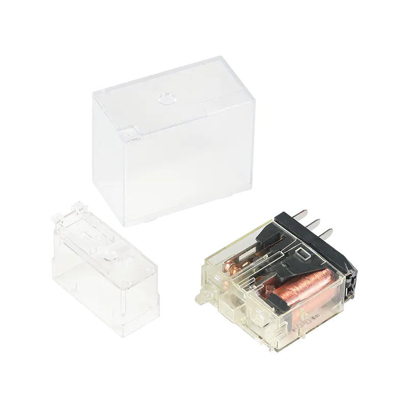
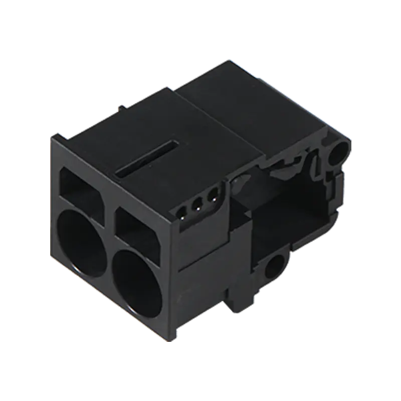
Circuit boards keep shrinking while the number of signals and power lines they need to carry keeps growing, and that pressure lands directly on the connector hardware tying one board to another or to an external wire harness. Electronic Board Connectors built for today's denser layouts work with pin spacing measured in fractions of a millimeter tighter than a design from just a few years back, which changes what precision actually means at the mold and assembly stage.
Pin Pitch Tolerance Decides Whether Dense Boards Assemble Cleanly
A board-to-board connector spec'd at a fine pitch leaves very little room for dimensional drift between the mold cavity and the finished plastic housing, since even a small deviation across dozens of closely spaced pins compounds into a misalignment that keeps the mating half from seating properly. Injection molding Electronic Board Connectors at this pitch calls for tighter cavity tolerances and more consistent shot-to-shot repeatability than a wider-pitch design ever required, particularly across a full production run rather than only the initial samples pulled from a new tool. Getting this right at the mold design stage avoids downstream assembly problems that are far more expensive to trace once a board has already gone through reflow, since a pitch mismatch that shows up after soldering usually means scrapping the whole assembly rather than a single component.
Mating Cycle Life Matters Especially On Connectors Meant To Be Unplugged
A board connector built into a sealed, permanently assembled product only mates once, but Electronic Board Connectors used on modular or field-serviceable equipment get disconnected and reconnected repeatedly over the product's service life. Contact spring geometry and plating both influence how many mating cycles a connector holds up to before contact resistance starts drifting, and that number matters far more for a connector on a swappable module than one buried inside a sealed enclosure. Gold or gold-flash plating over a base contact metal extends that cycle life noticeably compared with a bare tin contact, at a cost trade-off that makes sense on a connector expected to see hundreds of disconnections rather than one permanent assembly. Designing housing and contact geometry with a target cycle count in mind, rather than treating durability as a single pass-fail spec, is what separates a connector meant for occasional service access from one built for genuinely repeated disconnection.
Keying Features Prevent Misalignment During Automated Assembly
Polarized housing shapes and asymmetric pin layouts on Electronic Board Connectors exist specifically to make an incorrect connection physically impossible, which matters more as automated pick-and-place assembly lines handle boards at speeds no human inspector realistically tracks in real time. A keying feature molded slightly off from spec can still look correct to the eye while creating enough resistance during automated insertion to slow down a production line, and in a worse case allow one of these Electronic Board Connectors to seat at a subtly wrong angle that only surfaces once the assembled board fails a functional test. Building keying tolerance into the same mold precision discipline used for pin pitch keeps this protection working the way it was designed to, rather than becoming a feature that exists on paper but drifts in practice.
Pitch tolerance, mating cycle durability, and keying precision all trace back to the same injection molding discipline behind Electronic Board Connectors, whether the end application is a board buried inside a sealed appliance or a module a technician swaps out in the field.